Mixing equipment comprising a vessel and at least one axial hydrofoil imepeller
The agitator, which was developed at the Faculty of Mechanical Engineering of the Czech Technical University in Prague within the framework of the TAČR project and is the essence of the described result, was designed to optimize its energy requirements during the batch homogenization process.
Specifically, the application focused on the field of wastewater treatment technology, in which the goal is to ensure the creation of sufficiently large clusters of waste substances in water so that they can subsequently be better separated, and the entire water treatment process is energy efficient. Before flocculation, a coagulant is injected into the purified liquid, which helps to create larger agglomerates of primary particles, the dimensions of which are so small that they cannot be separated from water by commonly available and energy-saving separation processes. Therefore, when the batch is mixed, it is necessary first to disperse the coagulant throughout the entire volume of the batch, which requires a higher mixing intensity, and then to ensure that larger particle clusters are formed, which requires less intensive mixing, during which agglomerates form due to mutual contacts between primary particles and already formed clusters.
The described result is an axial high-speed impeller with large-area blades, whose shape and size are hydrodynamically optimized
to minimize the energy requirements for mixing during the coagulation and flocculation processes. The designed impeller consists
of a hub and two to six blades attached to it, whose shape and size are the main essence of the given result. An example of
the impeller with positions referring to its essential parts is shown in Fig. 1. The blades (2), whose original shape is based
on a trapezoid, are diagonally rounded along the axis (3) leading from the inner corner of the leading edge of the blade (4)
to the opposite outer corner of the trailing edge of the blade (5) and are attached to the hub (1) on their shortest side.
To minimize shear stress peaks, the inner (4) and outer corners (6) of the leading edge of the blade are rounded the same
way as the outer corner (5) on the trailing edge. For technological reasons, the rounding of the blade can be replaced by
its partial bending so that the envelope of the bent blade corresponds to the envelope of the rounded blade. The number of
diagonal axes for bending depends on the size of the mixer. All axes for partial bending are parallel to the original diagonal
axis for rounding (see Fig. 1 right). This modification is advantageous, especially with regard to the technological possibilities
in the production of larger mixers for real operations.
![[pracoviste/12118/projekty/Mixing_device/image1.png]](https://fs.cvut.cz/content/images/pracoviste/12118/projekty/Mixing_device/image1.png "Optimized impeller with diagonally rounded blades")
![[pracoviste/12118/projekty/Mixing_device/image2.png]](https://fs.cvut.cz/content/images/pracoviste/12118/projekty/Mixing_device/image2.png "Optimized impeller with gradually bent blades")
Fig. 1. Optimized impeller with diagonally rounded (left) and gradually bent (right) blades.
The radius of curvature of the blades was also optimized during the design of the impeller. Fig. 2 shows two examples of agitator
curvature variants, the effects of which were tested in the research. From the point of view of coagulation and flocculation,
it is advantageous to use agitators with a larger radius of curvature of the blade.


Fig. 2. Tested impeller variants with smaller (left) and larger (right) blade radius.
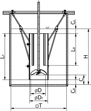
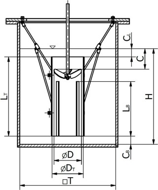
For proper function of the impeller, not only its shape is important, but also its correct location in the vessel. The plan shape of the vessel can be circular, square, or rectangular. Variants of the mixer location in the vessel are shown in Fig. 3. The mixer can be located centrally in the vessel (Fig. 3a), eccentrically (Fig. 3b), or also together with a draught tube, which allows increasing the range of the impeller's pumping effect to greater depths in deeper tanks (Fig. 3c, 3d). In such a case, the mixer can be located both in an arrangement with pumping toward the bottom (Fig. 3c) and with pumping toward the liquid level (Fig. 3d). In the case of deep tanks, it is also possible to choose a variant of a multistage stirrer in which several impellers are placed one above the other on a common shaft.
For each of the variants mentioned above, certain recommendations apply in terms of the appropriate choice of the diameter
of the impeller and its location above the bottom or below the liquid level. The specific parameters depend on the properties
of the mixed batch and the purpose of mixing. For coagulation and flocculation processes, square tanks are often used, the
depth of which is greater than the dimensions of the sides. For such an arrangement, it is appropriate to choose an impeller
in a draught tube of a diameter equal to a third of the vessel diameter with pumping direction to the liquid level. In the
case where the depth of the tank corresponds approximately to the length of the edge of the tank, it is more advantageous
to choose an arrangement without a draught tube with a centrally located down-pumping impeller having a diameter of a third
of the diameter of the vessel. If the tank has a circular cross section, it is necessary to supplement the tank with baffles
that prevent the formation of a central vortex, or to place the impeller eccentrically in the tank.
For each specific arrangement variant, it is necessary to know the process characteristics of the mixer in the given arrangement.
These characteristics include in particular the power consumption characteristic, which gives the relation between the impeller
power consumption and its rotation speed, the pumping characteristic, which describes the pumping efficiency of the mixer
(the amount of liquid pumped by the impeller under given operating conditions), and the homogenization characteristic, which
indicates the dimensionless time required to achieve a certain degree of homogeneity in the mixed batch. All these characteristics
were determined for all basic arrangement variants during the research and development of the mixer and are an integral part
of the license agreement, on the basis of which the know-how is transferred to other parties (equipment manufacturers).
![[pracoviste/12118/projekty/Mixing_device/image5.png]](https://fs.cvut.cz/content/images/pracoviste/12118/projekty/Mixing_device/image5.png) |
![[pracoviste/12118/projekty/Mixing_device/image6.png]](https://fs.cvut.cz/content/images/pracoviste/12118/projekty/Mixing_device/image6.png) |
| a) | b) |
 |
 |
| c) | d) |
Fig. 3. Agitator arrangement in the vessel: central (a), eccentric (b), with a draught tube and impeller pumping toward the bottom (c), with a draught tube and impeller pumping toward the liquid level (d).
Patent:
https://isdv.upv.gov.cz/webapp/!resdb.pta.frm
Articles:
The result was applied in practice in the form of a license agreement concluded by FME CTU as the owner of the result with the company ENVI-PUR, s.r.o., which is a major Czech manufacturer of water purification and treatment equipment with global representation. The full text of the license agreement is attached to this accompanying text, including an example of an appendix for one selected implemented application.
Examples of real-world application of the result:


")
")
")
")
In collaboration with:
Contact:
prof. Ing. Tomáš Jirout, Ph.D.
Department of Process Engineering FME CTU in Prague
E-mail: tomas.jirout@fs.cvut.cz
Phone: +420 224 353 243