Wear of electrodes in resistance welding depending on the type of final surface layer of welded sheets
For the experiment, supplied galvanized steel sheets with a total thickness of h = 0.7 mm and designation:- HX180BD+ZE100 (Zn)
- HX180BD+ZE100+ Inorganic coating based on sulfur compounds (SS)
- HX180BD+ZE100+ Inorganic coating based on Zn salts (SZ)
- HX180BD+ZE100+ Inorganic coating based on acidic aqueous compound (PSV)
| C | Si | Mn | P | S | Al | Nb | Ti |
| ≤ 0,06 | ≤ 0,5 | ≤ 0,7 | ≤ 0,06 | ≤ 0,025 | ≥ 0,015 | ≤ 0,09 | ≤ 0,12 |
Table 2: Mechanical properties of steel HX180BD ZM100
| Rp 0,2 [MPa] | Rm [MPA] | Ductility A80 [%] |
| 180-240 | 290-360 | 34 |
For welding, the PMS 11-4 resistance welding press from Dalex (Fig. 1 left) with interchangeable armature, pneumatically driven, was used. It is a mid-frequency [1000 Hz] inverter. The welding press is equipped with a 13-time control unit with 64 welding programs. The unit type is MEGA 1 MF 13Z64P QSF/S.
To "produce" worn caps, a certain number of welds were made on a large sheet. After a certain number of welds, a set of 12 smaller samples intended for mechanized shear testing and metallography was welded.
On 11 welded smaller samples, mechanized shear testing was performed on the LabTest 5.100 SP1 electromechanical testing machine (Fig. 1 right). The nominal load of the machine was 100 kN. The result of this test was the maximum force Fmax [kN] needed to break the weld joint. The diameter of the weld point was measured on the broken samples.
To detect internal defects, the last welded sample from each set of 12 samples was subjected to metallographic examination.
The contact surface of the interchangeable welding caps will subsequently be scanned on the RedLux device (RedLux Ltd., Southampton,
UK) outside the research task. This device consists of two sliding and two rotating axes, which use air bearings to achieve
higher movement accuracy (Fig. 2). The rotating axes move with the sample, and the sliding axes move with the sensor.
 and tensile testing equipment (right)")
Fig. 1 Welding equipment (left) and tensile testing equipment (right)
![[pracoviste/12133/projekty-skoda/resistance-welding/image3_result.jpg]](https://fs.cvut.cz/content/images/pracoviste/12133/projekty-skoda/resistance-welding/image3_result.jpg "RedLux device for scanning the worn (contact) part of the electrodes")
Fig. 2 RedLux device for scanning the worn (contact) part of the electrodes
First, the welding parameters for the DALEX PMS 11-4 resistance spot welding press were optimized for the experimental material (HX180BD+ZE). The minimum weld diameter was set to 2.9 mm (based on the formula d=√3,5.t, where t=0.7t=0.7 mm is the sheet thickness), and the shape of the weld (weld nugget) had to be as symmetrical as possible. The electrode imprints must not exceed 20% of the sheet thickness. The penetration of the weld nugget into each sheet must be between 20% and 80% of the sheet thickness.
During the experiment, a set of worn electrode caps with defined wear was produced for each type of material mentioned. Each pair of caps (upper and lower electrode) created a different number of welds with repeated parameters (chosen according to the previous optimization). It is important to note that we are primarily interested in the upper electrode from each produced set of electrode caps, because unlike a welding robot, manual movement of the test sheets during the experiment causes wear on the lower electrode, which can affect the purity of the experiment. The chosen number of welds for the wear degree were: 1, 10, 25, 50, 75, 100, 150, 200, 250, 300.
For sets with the number of welds ranging from 25 to 300 during the experiment, samples were prepared for subsequent mechanized shear testing and metallography. For each set of worn electrode caps, 12 samples were prepared, i.e., for the set labeled 25, welds 19 to 31 were placed on individual sheets for further testing (11 samples for mechanized shear testing and 1 sample for metallography).
An example of the dependence of welding current size on the number of welds for the material HX180BD+ZE100 compared to others
is shown in Fig. 3.

Fig. 3 Dependence of the measured welding current size on the number of welds for the material HX180BD+ZE100
Fig. 4 shows the moving average of welding current values for the individual tested sheets. The comparison shows that all
three types of surface layers on the Zn coating reduce the contact resistance, leading to higher welding currents with the
same parameter settings. This increase in current is very pronounced with a small number of welds. From approximately 25 welds,
the welding current values "stabilize," with the Zn + SS coating being the only one to slightly fall below the pure Zn coating
in terms of welding current values. The most significant increase in welding current throughout the electrode's (or electrode
cap's) lifecycle, with an increasing trend, is exhibited by the Zn + PVS coating.

Fig. 4 Overall comparison of the dependence of welding current size on the number of welds
 on the number of welds")
Fig. 5 Example comparison of the dependence of welding current size (for samples used in mechanized shear testing) on the number of welds
The following image shows macro welds for different types of coatings performed with electrode caps worn by a defined number
of welds.
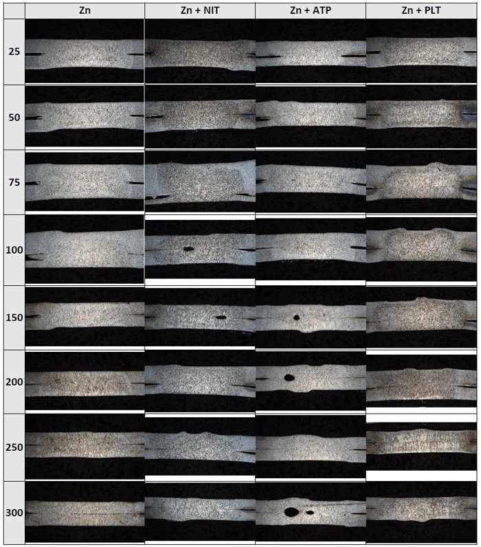
As can be seen from the macro welds, all coatings except pure Zn show significant surface morphology changes due to electrode sticking to the welded coating. This sticking occurs due to intense diffusion between the electrode cap and the coating. Detailed chemical analyses using an electron microscope would be necessary to describe the diffusion mechanisms.
RedLux – morphology of the contact surface of electrode caps
In addition to the above analyses, the worn contact surfaces of the electrode caps were scanned and these scans were compared
with scans in the pre-wear state. An example of what the result of such a procedure looks like is shown in Fig. 6.

Fig. 6 Example of evaluating results obtained by scanning the contact surface of the electrode cap on the RedLux device
The results of the experiments show that the final surface layer SS, SZ, and PVS does not have a significant impact on the weld strength. Up to 150 welds, no particular difference is noticeable. Beyond 150 welds, in some cases (PVS), diffusion bonds often form (welds break at the interface), and the scatter of maximum forces required to shear the sample increases. This corresponds with the measured diameters of the weld points.
The most significant differences in the examined surface layers are in their impact on the weld surface morphology due to electrode cap sticking to the coating of the welded material. This sticking significantly affects the welding process, as even after a very low number of welds, considerable force is needed to detach the sheet from the electrode. Solutions include regular cleaning of the contact surface or using technology that employs sliding tapes over the electrode contact surface.
In collaboration with:

Contact:
doc. Ing. Marie Kolaříková, Ph.D.
Department of Manufacturing Technology FME CTU in Prague
E-mail: marie.kolarikova@fs.cvut.cz
Phone: +420 224 352 628